Hardware
PCB options for DIY builds
Here are some option that can be used to build a ispindel device (DIY) based on ESP8266 / ESP32 Mini boards
Here are some option that can be used to build a gravitymon device (DIY) based on ESP32
Gravitymon PCB options for DIY builds
PET Casing option
PILL Casing option (work in progress)
I have now also created my own PCB design for Gravitymon which enable all the features not available in most other projects. I’m working on more options but this is a slow process since delivery of prototypes take time.
My PCB’s are designed in Kicad and stored in my repository mp-se/pcb_designs
You can also order the PCB from PCBWAY here
Currently i’m also working on a PCB for the PILL casing with the Waveshare ESP32c3 Zero board.
iSpindle based on esp8266
You can of course also use an ESP8266 based iSpindle design and flash it with the Gravitymon firmware. This is the original design and there are many resources available on how to build this.
Cuckoo Tilt
You can now also use the Cuckoo Tilt which can be found on chineese marketplaces. This is a ready to use device that can be flashed with the Gravitymon firmware. It has a built in battery and charging circuit and is based on the ESP32c3. The tilt sensor is an ICM-42670-p which is supported by Gravitymon. There firmware is a custom version of Gravitymon so support is not a problem.
There is no serial usb port exposed on the device but its possible to flash the device using some soldering and usb-ttl adapter in case its gets bricked.
Supported ESP boards
From v2.3 i have changed the main boards that I support as part of this project and the focus is now moving towards ESP32 based boards. The main reason is that the ESP8266 is old and resources are limited for adding new features. The original iSpindle design is starting to get older and new and better boards and components exist today.
For the pcbs make for the ESP8266 some of the features will not be available but I’m currently working with some pcb designeers to create new options that full utilize the features in Gravitymon.
I’m working on adding more ESP options and I will add the pinouts once they have been confirmed.
Board |
SDA |
SCL |
OneWire |
Battery |
Reset |
Charging |
Config |
|---|---|---|---|---|---|---|---|
Lolin ESP8266 |
D3 |
D4 |
D6 |
A0 |
EN |
n/a |
D8 / D7 |
Lolin ESP32 c3 mini |
7 |
6 |
A0 |
A3 |
EN |
A1 |
A5 / A4 |
Lolin ESP32 s2 mini |
A17 |
A15 |
A8 |
A2 |
EN |
A6 |
A10 / A11 |
Lolin ESP32 s3 mini |
A17 |
A15 |
A12 |
A1 |
EN |
A11 |
A9 / A10 |
Waveshare ESP32c3 Zero |
IO6 |
IO7 |
IO5 |
A0 |
n/a |
A4 |
A1 / A3 |
Tenstar ESP32c3 super mini |
IO7 |
IO6 |
A0 |
A3 |
n/a |
A4 |
IO10 / A1 |
Cuckoo Tilt (ESP32c3) |
7 |
6 |
A0 |
A3 |
n/a |
n/a |
A5 / A4 |
Olimex ESP32C3 DevKit Lipo |
IO1 |
IO0 |
IO5 |
IO3 |
n/a |
n/a |
IO4 / IO20 |
Custom boards
Besides the standard boards listed here (which are tested and verified by me) there is also a possibility to add custom boards which are included in the builds and made available through this gihub repository. A list of these boards can be found here Custom boards. I cannot take full responsibility for these builds since I dont have access to these boards for testing.
Gravitymon PCB
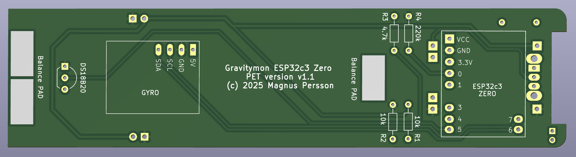
Waveshare ESP32c3 Zero using PET casing
This is my own design of a PCB for Gravitymon using the same PET casing as for the iSpindel. For building this you need:
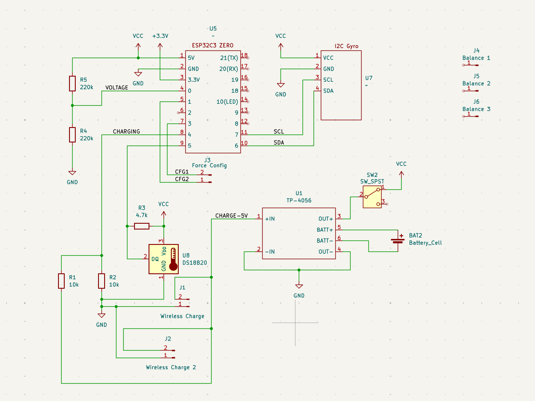
This is the schematic that is used for this design enabling all the features in Gravitymon.
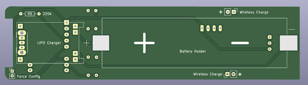
This is the back / front of the PCB design.
iSpindle based on esp8266
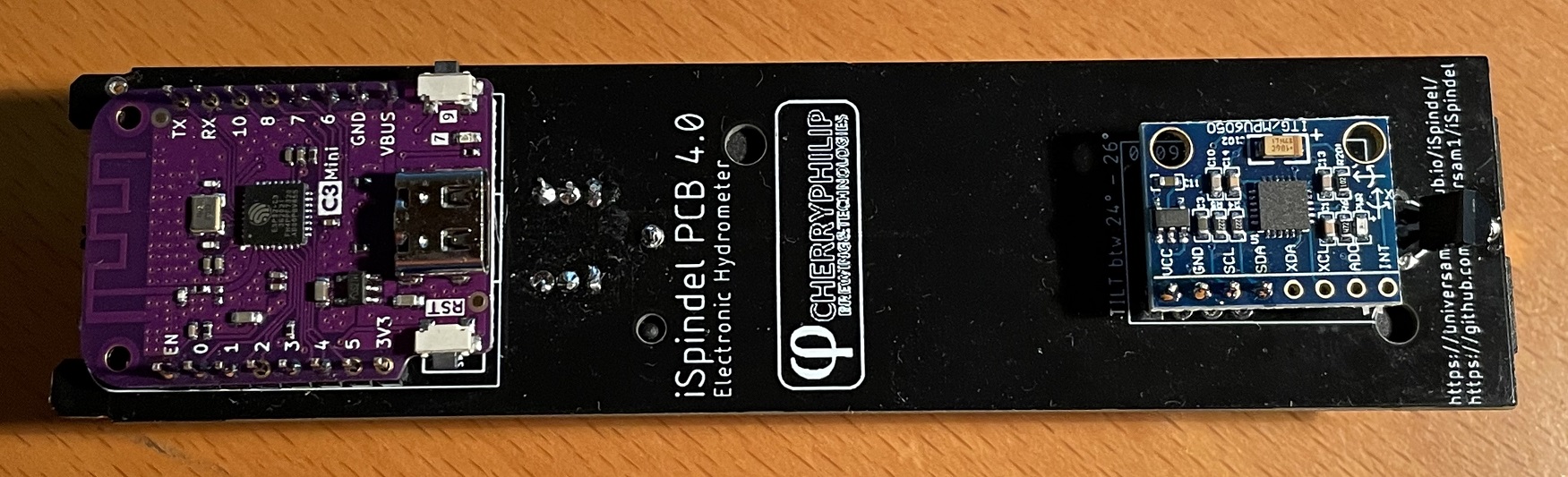
There are lots of resouces out there on how to build the hardware for an iSpindle so I will not go into details on that part. I typically use one of the excellent pcb boards that, for example the iSpindel PCB v4.0 from Cherry Philip. Here is one of my standard builds using an esp8266.
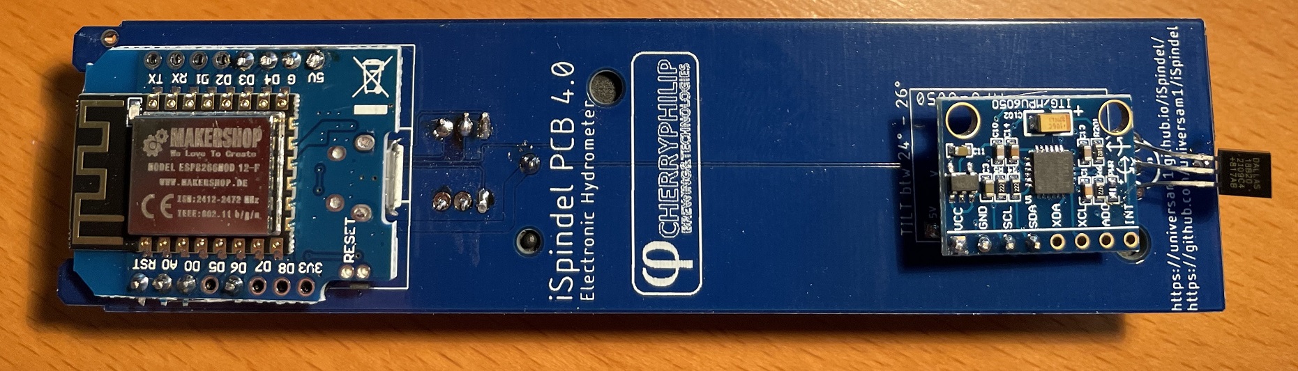
Schema for esp8266 build
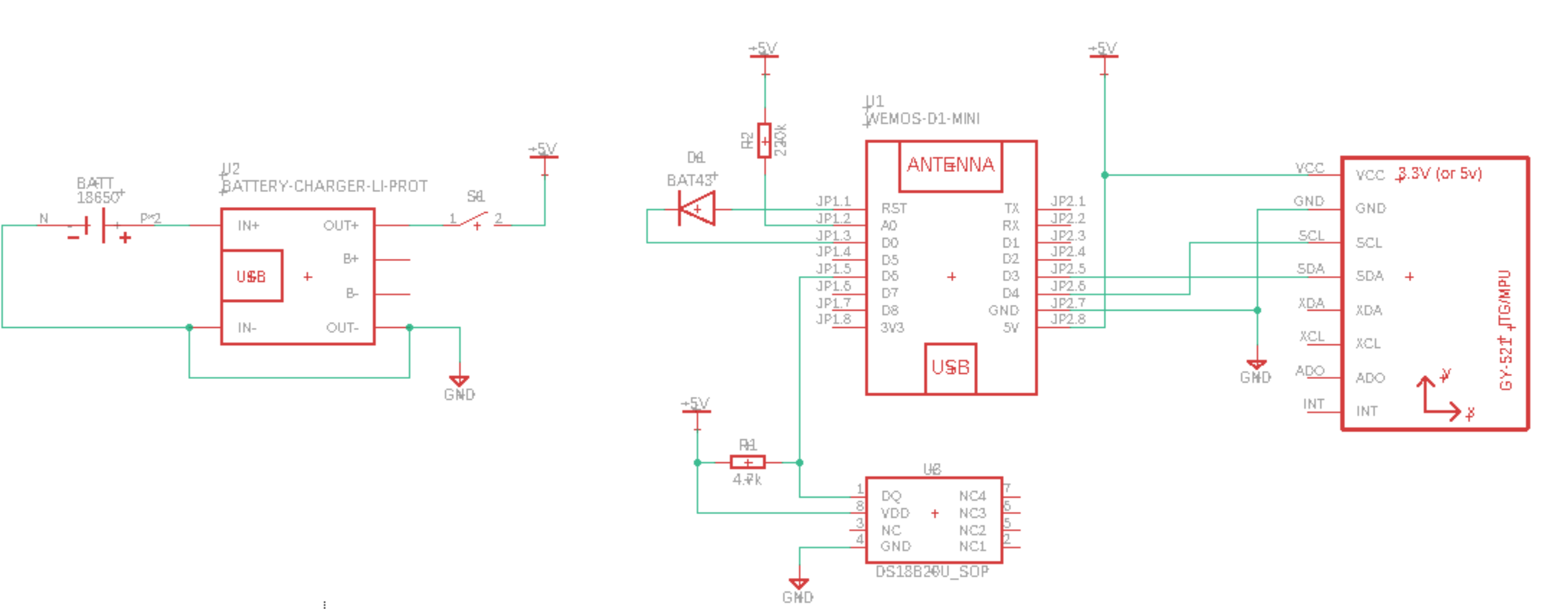
What is different for the ESP32
You need to add a resistor between Battery PIN and ground of 220k. The reason is that the esp8266 has a build in resistor for a voltage divider which the esp32 does not have. So in order to get a valid voltage (less than 2.3V on the analog pin. This depends on the board) on the analog pin this is needed. Once the modification is done you might need to adjust the voltage factor so the battery reading is correct.
The charing pin needs to be enabled in the configuration and when power is higher than 2.5V on that pin it will force the device into deep sleep until the power is lost. This is intended to be used with wireless chargers so when the device is charging its turned off. You might need to add a voltage divider and pull-down resistor for this to work correctly and not damage the ESP with more than 3.3V.
The charging pin can also be used for doing a reset of the device that does not have an exposed reset pin, this applies to the smaller boards like Zero or Super Mini boards.
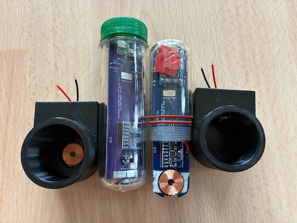
Wireless charging
Wireless charging is possible with the dedicated Gravitymon boards that has support for that. I have create to simple 3d models to show how to create a stand for the two options i have boards for. The models can be downloaded here 3d models and can be printed on a 3d printer.
For the PET casing the wireless charging coil is mounted on the bottom of the tube and for the PILL casing its on the side. You can hook up any DC charger that produce between 9-12V if you use the coils i recommend in my build.
Example: ESP32c3 mini
This is model is fully supported by gravitymon.
Here is an image of where I added the resistor for the voltage divider.

Modifications
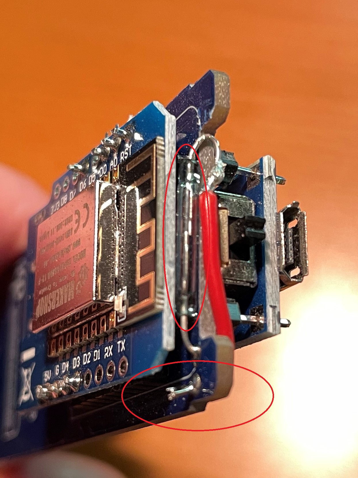
Adding a reed (magnetic) reset switch
A reed switch is a switch that reacts to magnetic fields. The ones I have tested are normally open and close in proximity to a magnet.
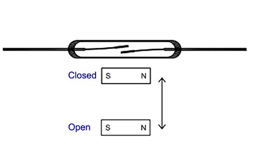
If this is connected to the reset button a magnet can be used to trigger a reset of the device. The image below shows how I mounted the iSPINDLE PCB v4.0 just under the cap. The lower red circle shows the reset connection point for the reed switch.
The reed switch is the glass tube visible under the esp8266.
Gyro options
Besides the standard MPU-6050 and MPU-6500 gravitymon now also supports the ICM-42670-p which can be obtained from Aliexpress as a development board. There is some work ongoing to create a new PCB based on this gyro. I will update with links when available.
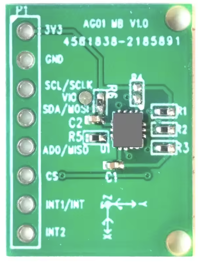
This is what I have used during my testing but it has a different orientation compared to the MPU-6050 but there is a setting in the device configuration that allows you to use the Y axis for tilt detection. The boards I used is pin compatible with the order board so current iSpindle PCB can be used.
Note
The ICM gyro does not have any calibration feature since they are calibrated from the factory. So mounting the at the correct angle is important.
Note
The ICM gyro boards that can be bought only support +3.3V power supply and most iSpindel boards use +5V to supply the gyro.